10+ deployment diagram
A deployment diagram shows the physical relationships among software and hardware components in the delivered system. The Main Purpose of the Deployment Diagram To represent the hardware topology of a system.

Hybrid Patterns For Deployment Hybrid Machine Learning
It maps software pieces of a system to the.

. Deployment diagrams depict the physical resources in a system including nodes components and connections. Deployment diagram represents the deployment view of a system. Lucidcharts diagram software is quick easy to use.
The deployment diagram maps the software architecture created in design to the physical system architecture that executes it. Each item in a deployment diagram represents a piece of. Represent how different hardware components are inter-connected and how these hardware.
Lucidcharts diagram software is quick easy to use. Windows 10 The following posters step through various options for deploying Windows 10 with Windows Autopilot or Microsoft Endpoint Configuration Manager. A deployment diagram shows components and artifacts in relation to where they are used in the deployed system.
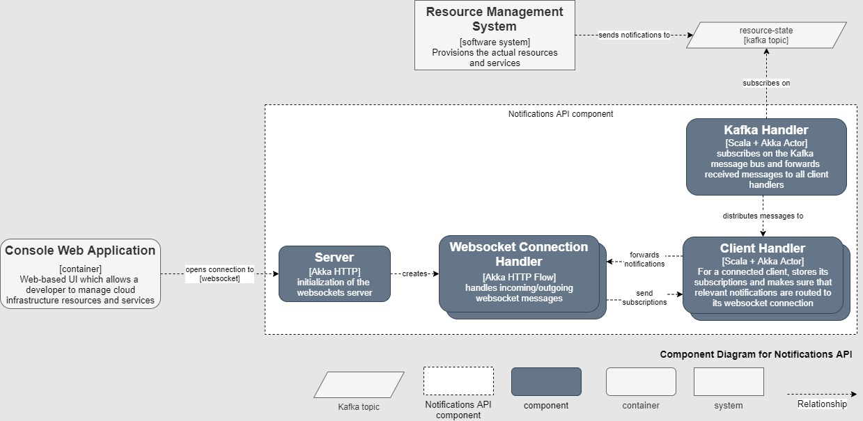
A Deployment diagram can be used to. A deployment diagram is a good place to show how. A component diagram defines the composition of components and artifacts.
Create UML Deployment Diagram with the drag and drop interface design with the. Capture the hardware that is going to be used to implement the system and links between different. It is related to the component diagram because the components are deployed using the deployment diagrams.
Deployment diagram shows execution architecture of systems that represent the assignment deployment of software artifacts to deployment targets usually nodes. Deployment diagrams show the physical arrangement of the hardware elements of a computer system. Ad Get the most powerful professional diagram software on the market.
The free UML diagram software provided by VP Online lets you create professional UML quickly and easily. A deployment diagram is a diagram that shows the configuration of run time processing nodes and the components hardware software middleware on hardware that. Ad Get the most powerful professional diagram software on the market.
Show the structure of the run-time system.

Field Notes How Sportradar Accelerated Data Recovery Using Aws Services Aws Architecture Blog
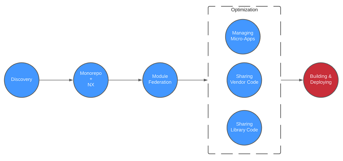
Building Deploying Part 8 Of 9 In Our Series That By Noah Jablonski Tenable Techblog Medium

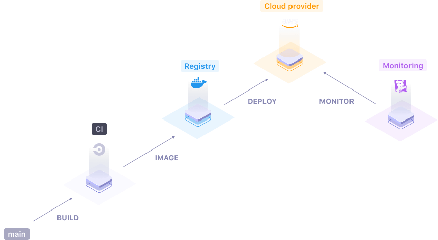
10 Continuous Delivery Tools To Consider Harness
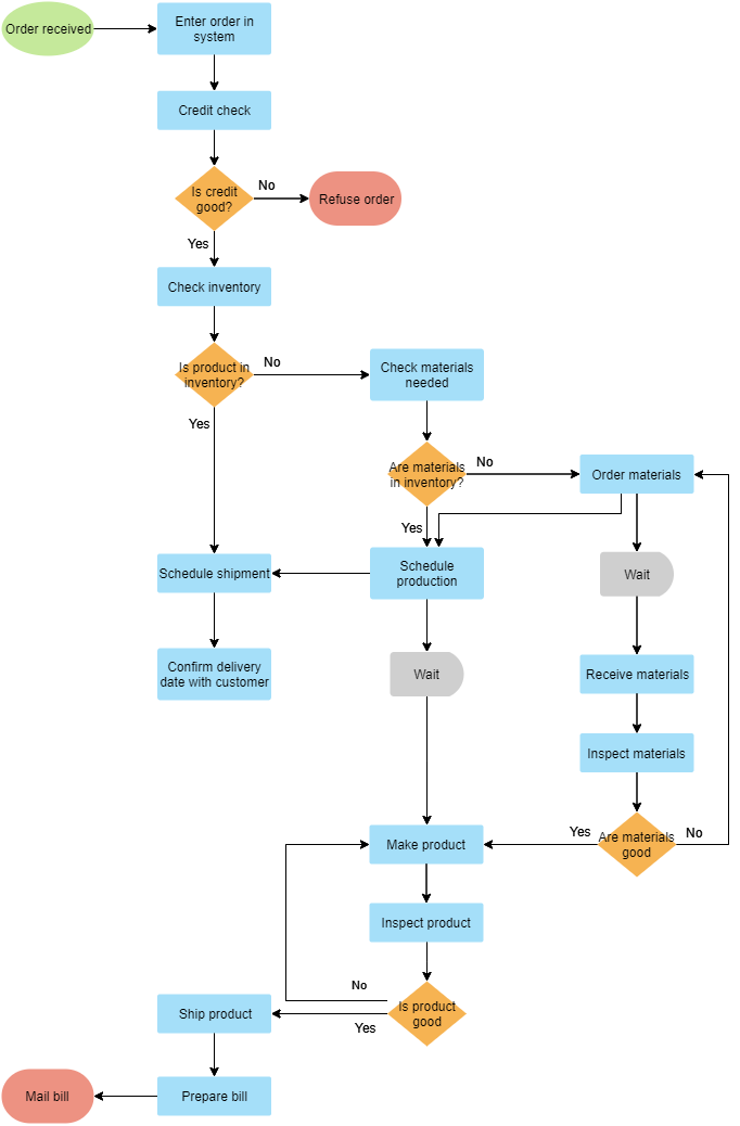
10 Flowchart Templates And Examples

Swim Lane Flowchart Symbols Swim Lane Diagrams Flowchart On Bank Flowchart Examples Swimlane Diagram For Banking System
How Are Deployments To Environments Being Done
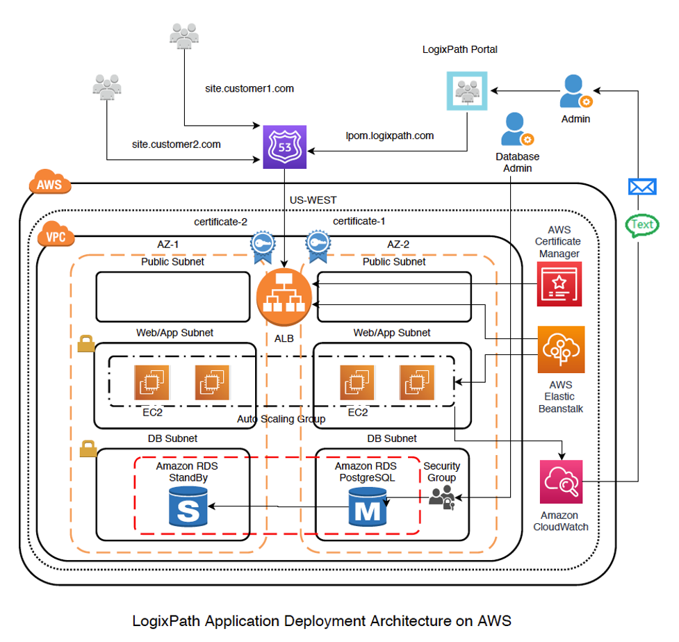
Logixpath S Application Migration From Pivotal Web Services To Aws Aws Startups Blog
We Have Open Sourced Our Deployment Engine
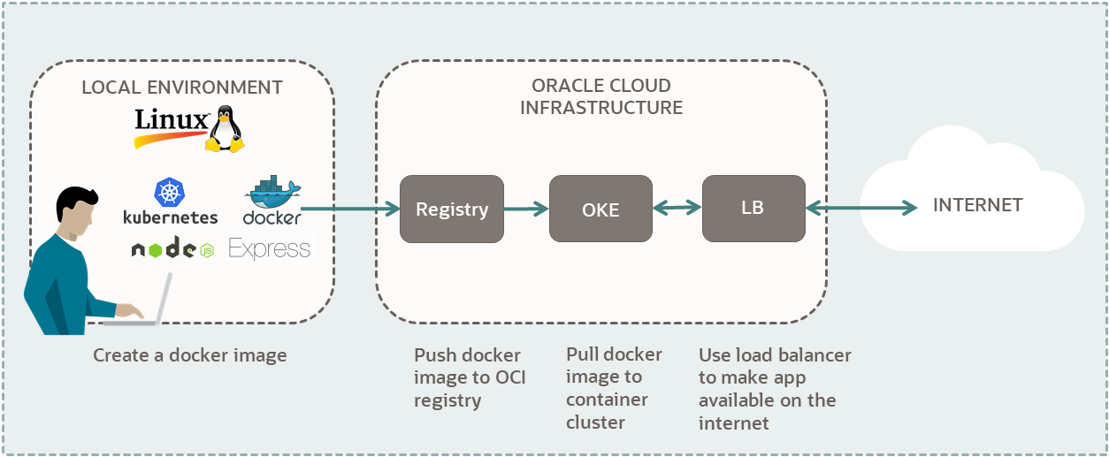
Kubernetes Deploy A Node Express Application
How To Drastically Save Time When Deploying Microsoft Office 365 Techrepublic
The Art Of Developer Documentation Digitalbuff
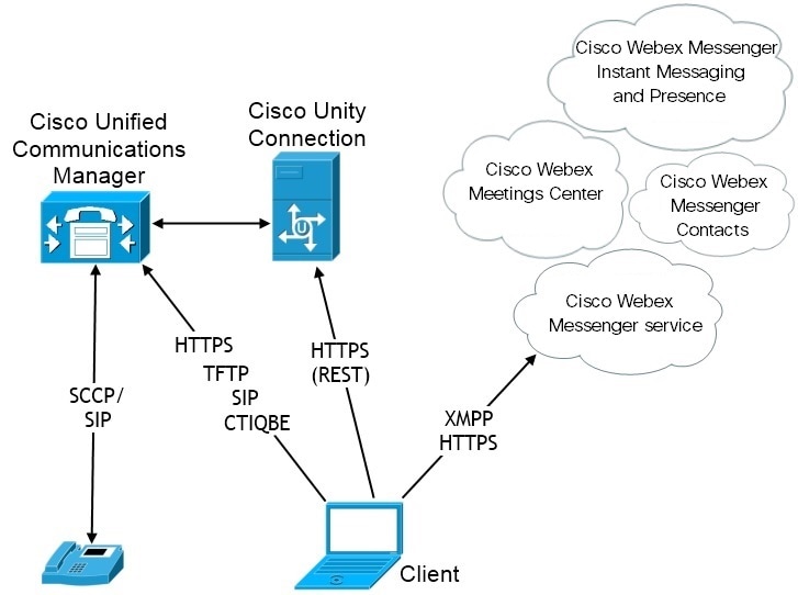
Planning Guide For Cisco Jabber 14 1 Deployment Scenarios Cisco Jabber For Android Cisco

Confluence Mobile Confluence
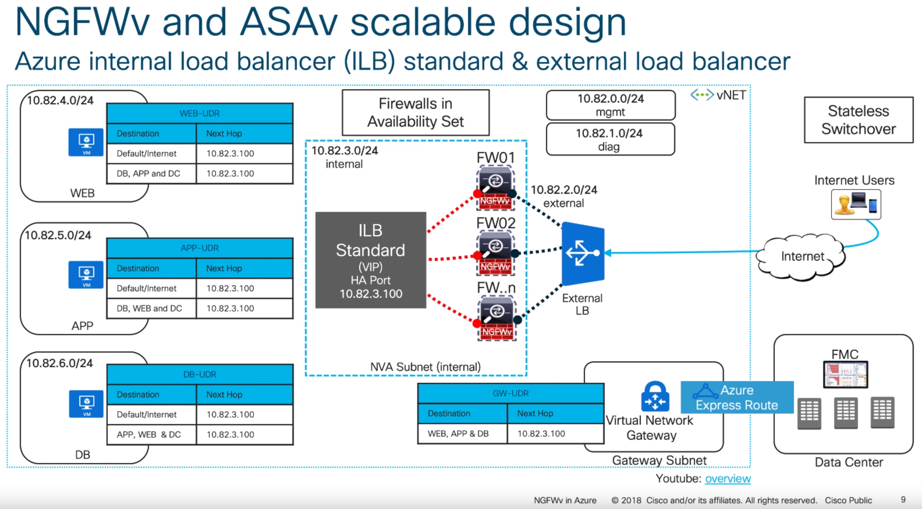
Deploying Cisco Virtual Appliances Ngfwv On Azure Jack Stromberg
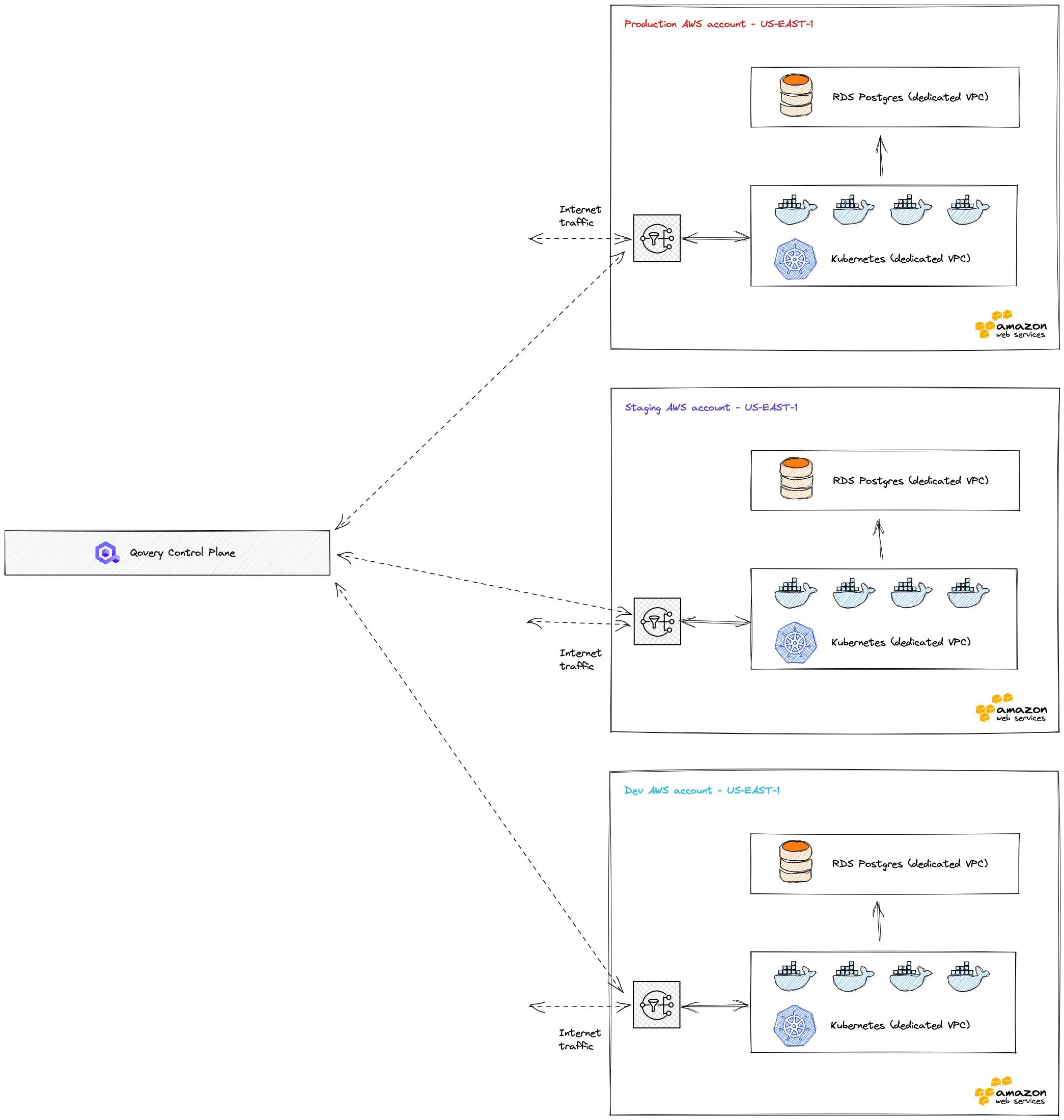
The Top 10 Aws Architecture Built With Qovery In 2022
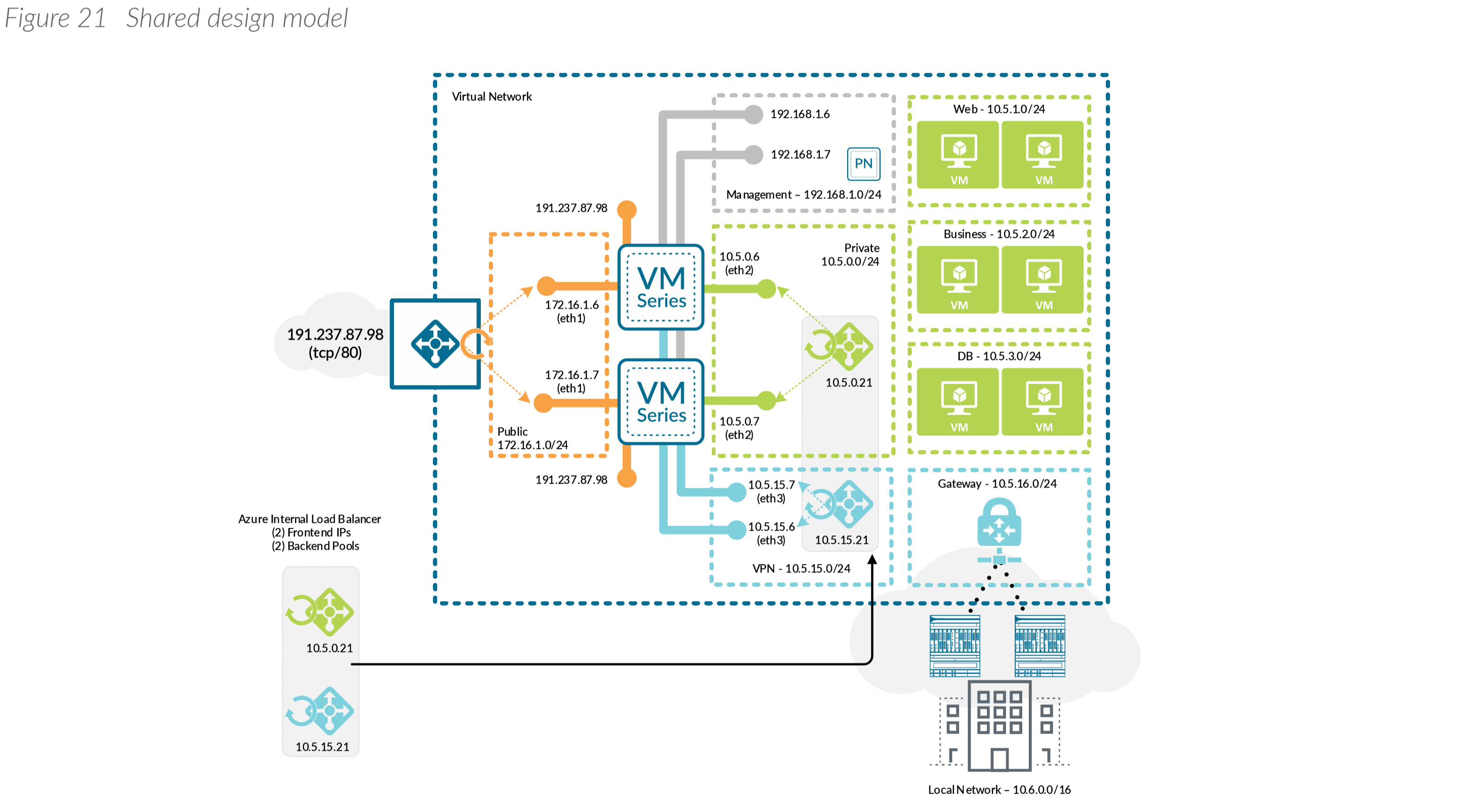
Azure Archives Jack Stromberg
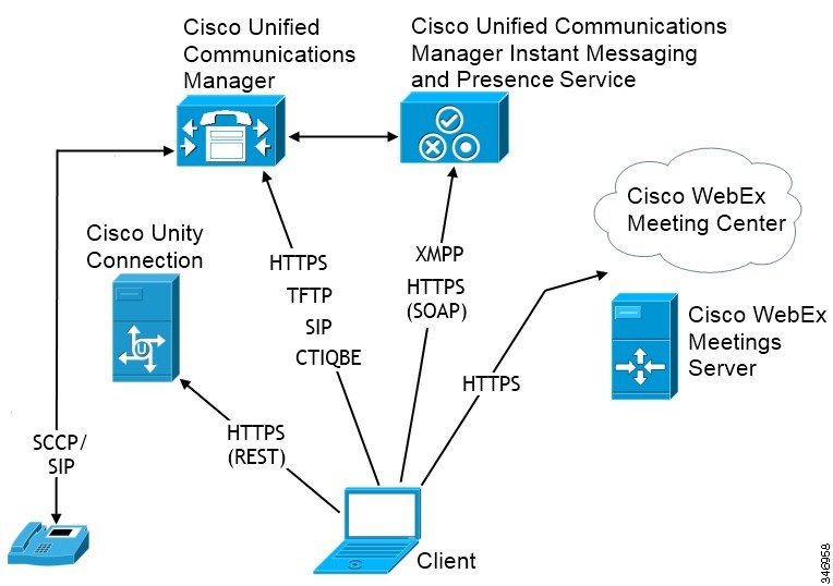
Planning Guide For Cisco Jabber 14 1 Deployment Scenarios Cisco Jabber For Android Cisco